One of the names associated with the making of snow ploughs today is James A. Cuthbertson Ltd of Biggar, Lanarkshire.
The company stated to trade in 1936 under the name James A. Cuthbertson, Biggar. It was in 1946 that it became a limited company.
In 1937 the company described itself as agricultural engineers. By 1946 it was also a general engineer, and in 1948 agricultural engineers and contractors. An advert in the Farming News on 15 December 1946 provides clues to the early specialities of the company. It described itself as “pioneers in mechanised draining”. The development and production of draining machinery and accessories was to become intimately associated with the Cuthbertson name.
In 1948 the company entered a drainage plough for the new implement award of the Royal Highland and Agricultural Society of Scotland. It was awarded a silver medal for it. The company described the plough as thus:
 “The plough will cut open drains to a maximum depth of twenty-two inches by a maximum width of thirty inches, at speeds varying from fifteen to thirty chains per hour, according to the nature of the ground, The plough consists of a simple sided mouldboard mounted at the rearward end of a box-girder beam, the whole being carried on a transport frame when not in operation and stabilised by a hinged sliding shaft whilst working. Beam and transport assembly are hinged about a steel rocker-pin, thus allowing the depth of the drain cut to be automatically controlled, irrespective of local undulations on the ground surface over which the transport wheels pass. Two steel cutter discs are pivotally mounted on the rocker-shaft, which is attached to the forward end of the beam, and a system of semi-elliptic springing allows the discs to rid over any obstruction and return to the pre-determined depth required. A hinged drawbar mounted at the extreme front of the beam gives a rough adjustment for depth control and has incorporated in it a shearing pin device which prevents damage to the implement should an immovable obstruction be encountered. The beam and components assembled thereon are raised into the carrying position by means of a steel cable, which should be operated by a suitable power winch mounted
  on the tractor. A spring-loaded catch is automatically engaged when the beam assembly has been raised to sufficient height and can be disengaged by the tractor driver without leaving the driving position. Any pre-determined depth of cut within the limits of the plough may be obtained by tilting the mouldboard by means of an adjusting screw situated at the extreme rear of the implement. This has the effect of altering the angle at which the share enters the soil in relation to the line of traction and so varying the depth of cut obtained. The spoil discharged by the mouldboard from the drain is removed a distance of one foot six inches back from the side of the drain by means of an adjustable, articulated pusher-blade which is mounted to the rear of the mouldboard.”
Another silver medal was to come for the company’s deep drainage plough with tile laying attachment in 1950:
“The Cuthbertson deep draining machine is designed to be hauled behind a heavy crawler tractor of 70hp to cut a drain up to a depth of 3ft, with a bottom width of 8in and a top width of 2ft 4in at the maximum depth, and to lay the tiles in perfect position, close and in line. The drain section is left ready to be covered in after the operation. The speed of the operation is 22 yards per minute.
The machine is a mild steel, electrically welded fabrication, except for the cutting share and wearing heel, which are of chilled cast steel. The machine consists primarily of a beam, transport frame and wheel, side and centre spring-loaded cutting discs, and a mould board tso shaped that it lifts the soil from the drain and deposits it on one side of the drain.
The tile laying attachment is attached directly behind the mouldboard, and the tiles are fed into this by hand from a trailer travelling alongside. The weight of the tiles being constantly fed into the attachment keeps the end butted closely together.
 Automatic depth control is incorporated in the machine, as without this factor it would not be possible to lay the tiles directly behind the machine, as the bottom of the drain would require to be levelled by hand. The bottom of the drain is in “V” formation to facilitate the centralising of all sizes of tiles in the drain.
The machine is lifted from the working position to the carrying position on the frame by means by means of a wire rope connected to a winch on the tractor. The wire rope is not in use when the plough is actually working, as the wheels can rise and fall, following the undulations of the ground, without altering the level of the drain being cut.”
The company also invented a number of other key machines for reclamation and forestry work. They included a bracken cutter (which won a silver medal from the Royal Highland and Agricultural Society of Scotland in 1949), a grass land rejuvenator and lime spreader in 1948, a double purpose forestry planting plough, double furrow, in 1949, and a lime spreading outfit in 1951. The company was also well known for the “Cuthbertson” half track for Fordson Major conversion, in 1951. It also invented and made the “Cuthbertson” trailer track in 1952.
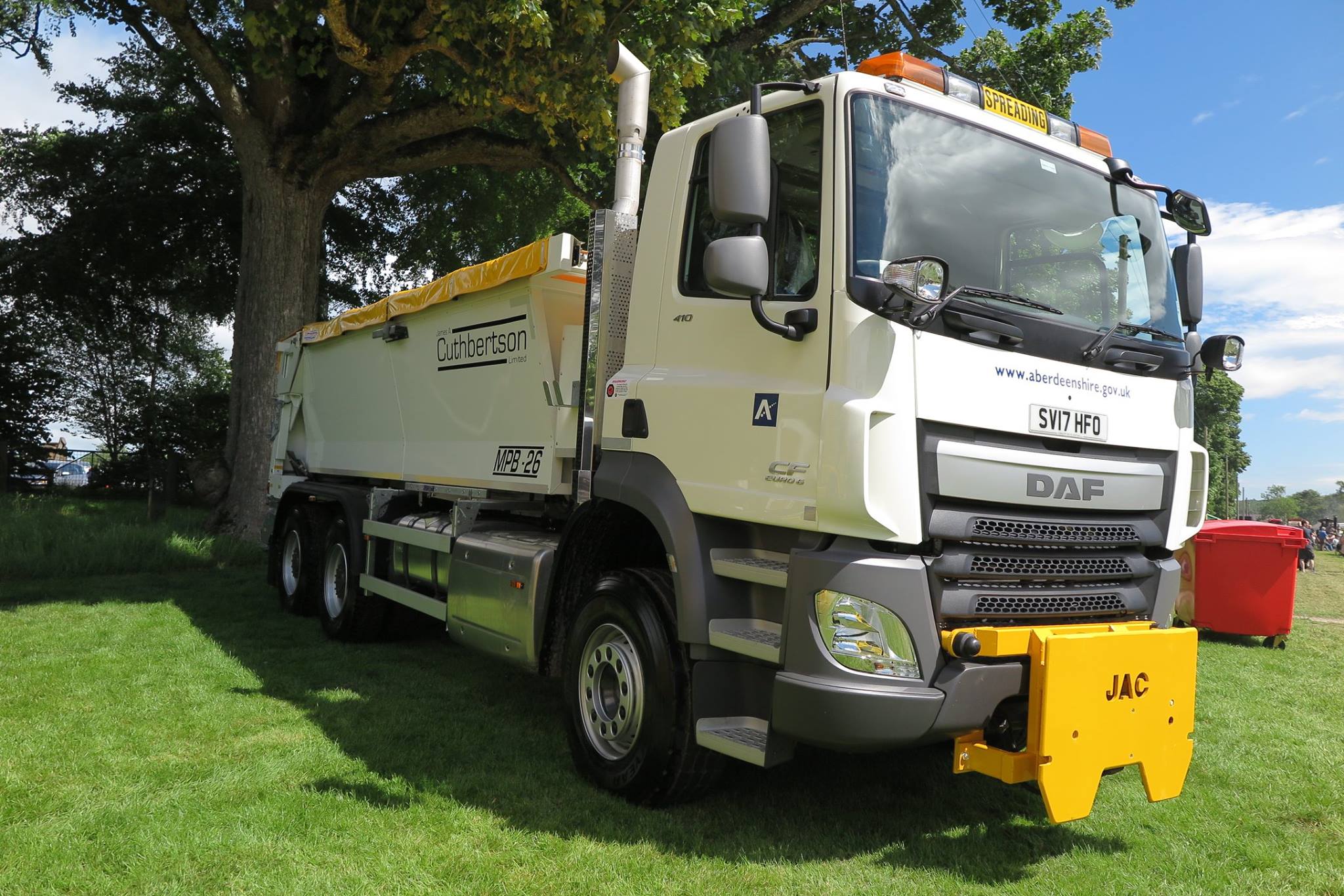
Today the company specialises mainly in winter maintenance equipment. In these wintry days you might just see a Cuthbertson snowplough. When you do, think about the important role that the company played in reclamation machines from the mid 1930s onwards!
The photographs of the Cuthbertson gritter were taken at the Bon Accord Steam Engin Rally, June 2017.
